While browsing my favorite local surplus store with Jay and Pat, Jay spotted a box full of old 3” arcade trackballs. Jay was all like “there is a box of arcade trackballs over there” and I was all like “shit yeah, I must have one”.
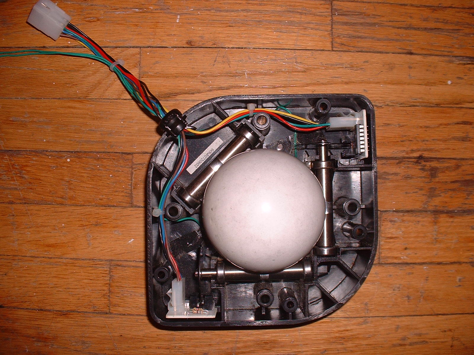
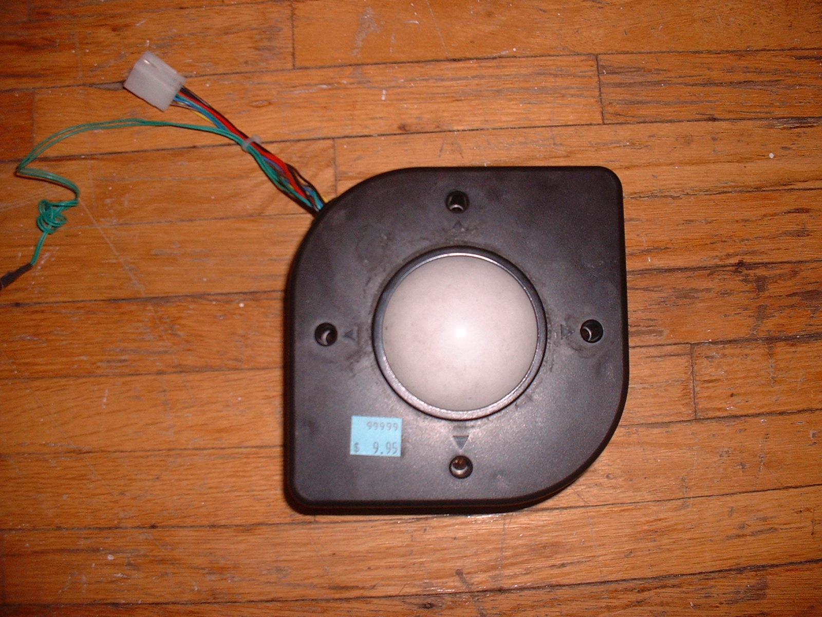
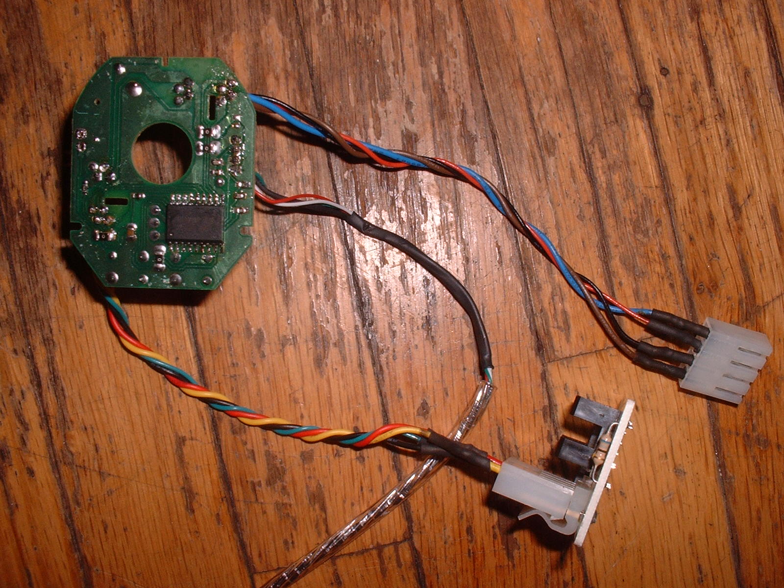
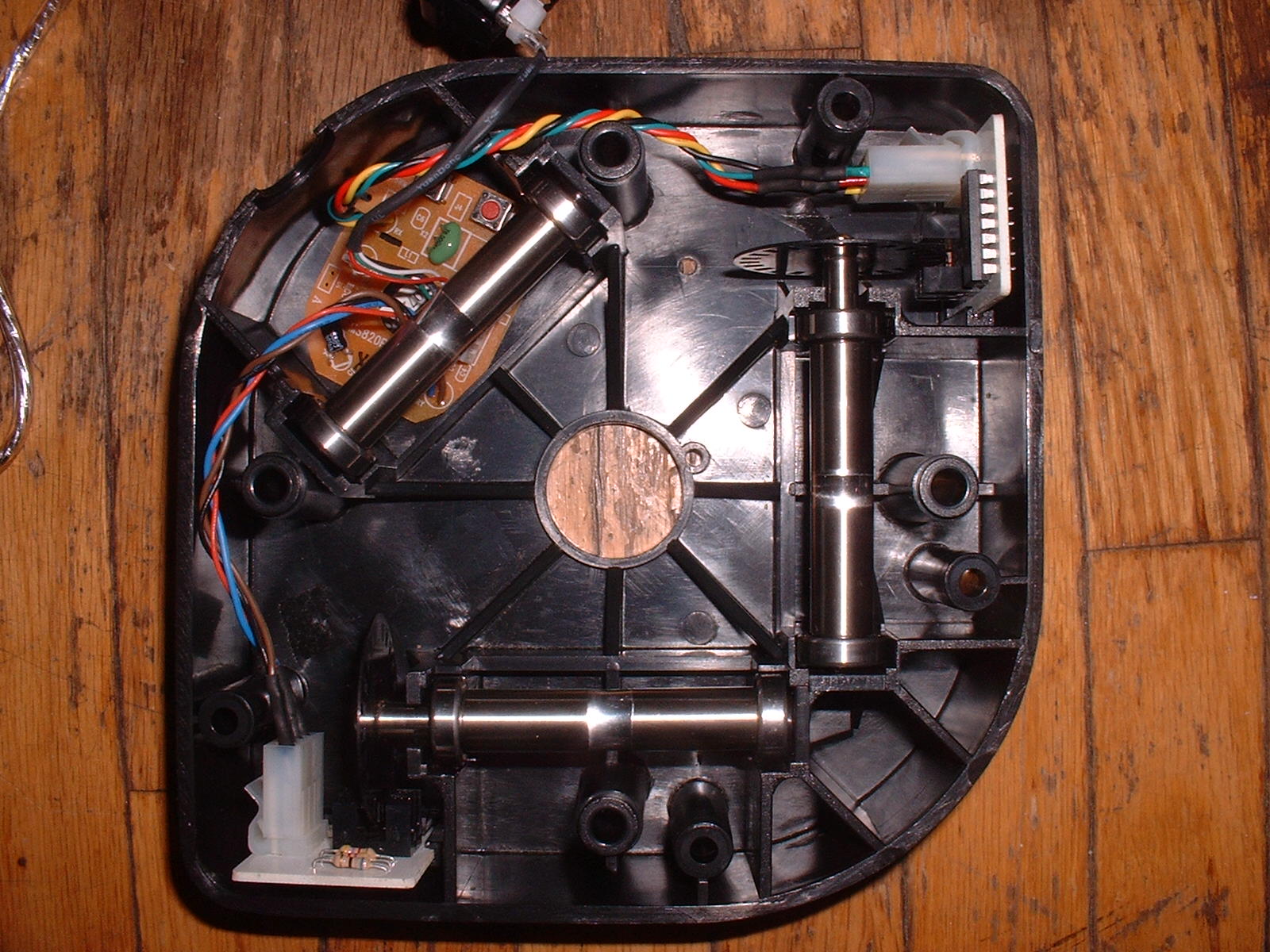
Just as I hoped, when I opened it up all the sensors where in place.
That plug is funny lookin’
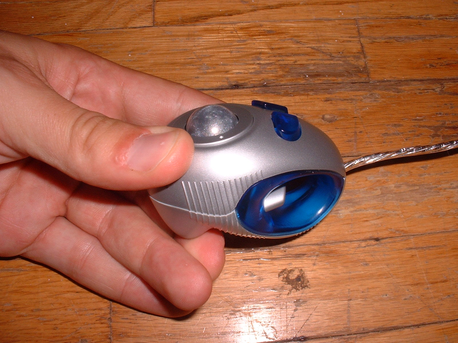
Yup this thing needs some more guts in order to work with some sort of MAME device (PowerBook, PC, XBox…). I went digging in my junk box and found this little gem!
It’s a hand held USB trackball (Fellowes Micro Track) and I bought it from a bargain bin some time ago. A few google searches shows lots of online retails that carry this mouse for around $15 US.
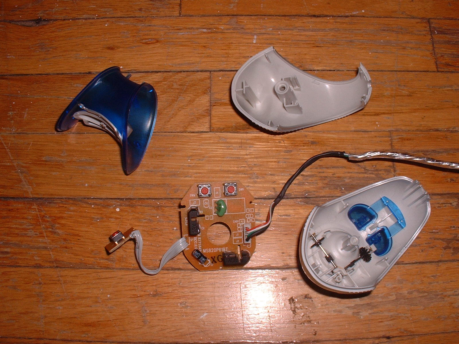
The insides look like this. The circuit board is nice and tinny and should tuck right inside the arcade trackball just nice. If you look closely at the rollers that the trackball rides on, you’ll see that it has some black discs with an array of teeth around them. As these teeth pass between both a light emitter and a receiver motion is detected. Mike Coates has published a nice guide on how to use a mouse to interface an arcade trackball with a PC and he recommends finding mouse internals with the same pitch of light to dark (ie: ratio of tooth width to space between teeth) as what the arcade trackball has. I choose to skip that and just start soldering.
Wiring it all up
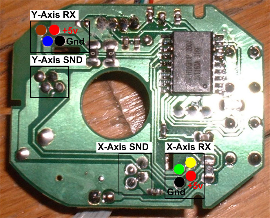
A bit of tracing with a multi-meter and I found all the solder points I was interested in. I am essentially replacing the light receivers on the mouse circuit with the ones in the arcade trackball. The arcade trackball has 4 wires coming from each circuit. The X-axis circuit on mine has red, black, green and yellow. The Y-axis has red, black, blue and grown. Black and red represent ground and +5v as usual but I’m not sure what the other colours do. However through some testing and a bit of trial and error I figured out where they need to go.

This mouse has a translucent component and a black component for each axis so I assumed the black component is the receiver. De-solder the receivers and solder in some light gauge wire from the junk pile. I re-used the molex plugs from the arcade trackball wiring by cutting off the plug and soldering the light wires to it (finishing off with a bit of shrink wrap). I didn’t bother removing the light emitters from the mouse circuit. I don’t know if this makes a difference or not.
Finish up by de-soldering the small PCB that contains the left mouse button and your trackball mouse guts are ready to go.
All done!
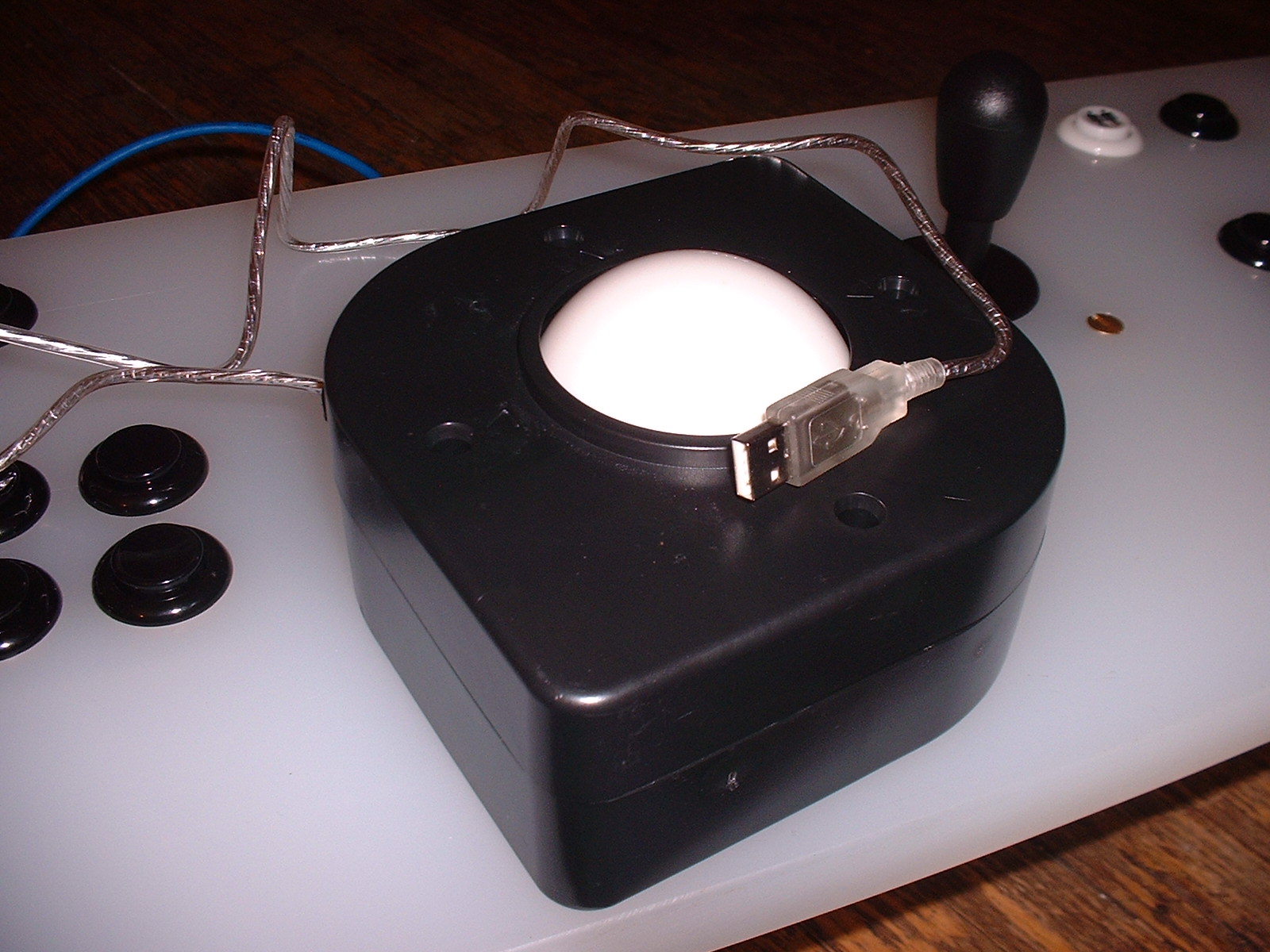
USB Arcade Joystick in all its glory, inside and out.
Caveats
In the picture of the arcade trackball internals, you might have noticed some deep groves in the roller pins. As it turns out, these groves cause the trackball to veer of course when you’re going for that really long drive in “Golden Tee 98”. I’m looking at having some new rollers machined and sourcing some new bearing to see if this helps the situation.