Disclaimer
The following work is based on the origional XirRemote by Squar0L. I have not changed the schematic of the origional design, infact, the only distinguishing feature of this guide is the fabrication of the pcb and the installation. This guide is intended as an alternative to the origional authors guide, after all choice is what makes the internet great.
Components
I purchased the bulk of my components at local electronic component retailers, however, you could just as easily order everything from Digi-Key or Mouser. Yes I purposly left out Jameco because I had a disapointing experience with them during this project.
| Item | Qty | MFG # | Digi-Key # | Min Qty | Unit Price |
|---|---|---|---|---|---|
| Sharp GP1UDxxxx | 1 | GP1UD267XK | 425-1118-ND | $1.33 | |
| PIC16F628 4MHZ | 1 | PIC16F628-04/P | PIC16F628-04/P-ND | $3.63 | |
| R1 10K | 1 | ERD-S2TJ103V | P10KBACT-ND | 10 | $0.067 |
| R2 47 | 1 | ERD-S2TJ470V | P47BACT-ND | 10 | $0.067 |
| C1 0.1u | 1 | ||||
| C2 47u | 1 | ||||
| D1 1N4148 | 1 | 1N4148 | 1N4148FS-ND | $0.07 |
You will also need some wire, some plugs/headers, and maybe an IC socket for the PIC. I will assume you have these items sitting in a junk pile somewere, otherwise go to the store and pick up some supplies. Buy some extras so you have them for the next time you tackle a project like this.
I was browsing the Digi-Key catalog of capasitors and I noticed they have surface mount capacitors and resistors which would have shrunk the pcb design down conciderably. If your goal is to make your design as small as possible, consider these surface mount components, I wish I had researched that before I started. :)
Tools
Along with the components listed above, you will need a few specific tools. One of which is a PIC programmer to flash the PIC16F628. I bought a simple DIY kit from Kitsrus. They sell a whole line of PIC programmers each varying in complexity. I choose K149 which has both a serial and a USB interface, however, the K128 looks like a much simpler design and uses USB power instead of an external power supply.
Kitsrus does not sell directly to the public, however, they seem to have distributers all over the world. I found a local distributer in Toronto called A1 Parts which turned out to be a gold mind of various parts and just general interesting things.
I used a photofabrication kit from MG Chemicals to make my PCB. This almost seems like overkill but I have it and it’s simple to use so I used it. If you have the means, I highly recommend picking one up.
Admitedly the photofabrication kit can be rather expensive. The initial cost isn’t nearly as bad as the cost of materials (presensitized copper clad, chemicals, etc). So if your not keen on dropping all that money into photofabrication, check out this site by Thomas P. Gootee. It’s a PCB fabrication method using toner transfer. I attempted it breifly with marginal success, however, my iron just wasn’t hot enough to make the transfer work.
Enough Talk, Get to the Soldering!
Receiver Module
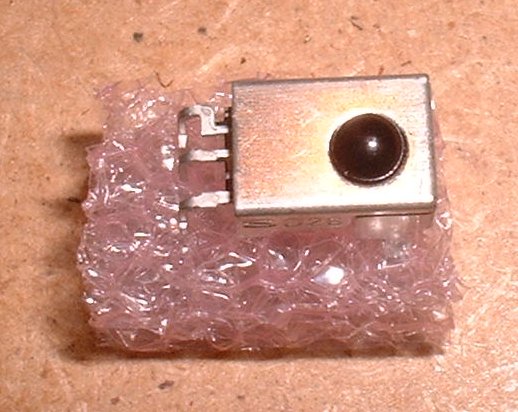
Ok, ok… I know your anxious to get started so here goes. This is the Sharp RF receiver I ordered from Digi-Key. Sharp manufactures a few different versions of this receiver so your not limited to the top oriented one that I have. Check out the Digi-Key catalog and Sharp spec for other types.
Keep the foamy bit the receiver is packaged in. This will come in handly latter to keep the receiver board held in place.
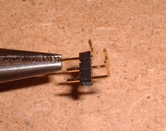
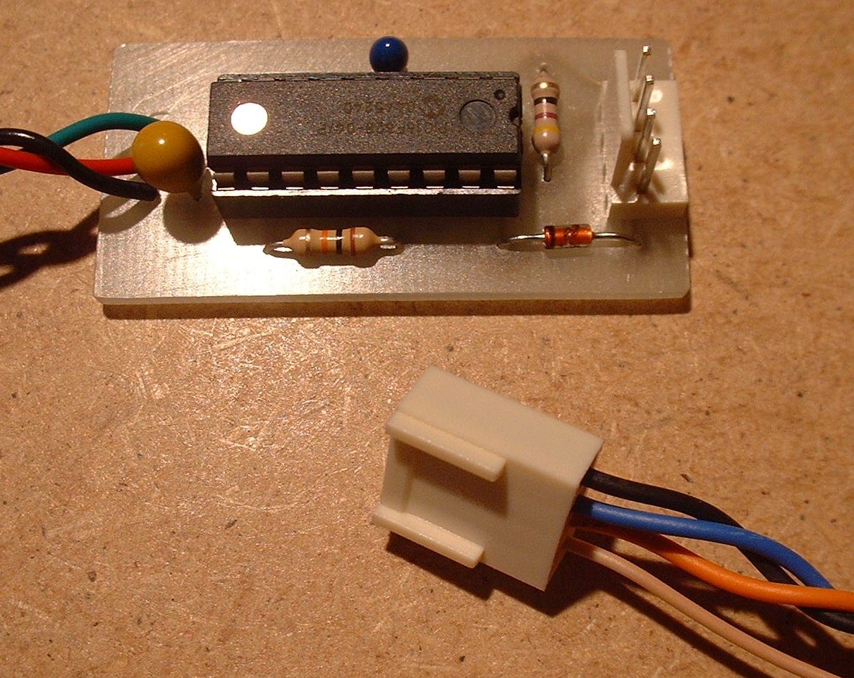
My goal is to build a compact modular board for the receiver. Therefore these tall right angle headers just wont due. Push the pins through as shown to give the header a lower profile.
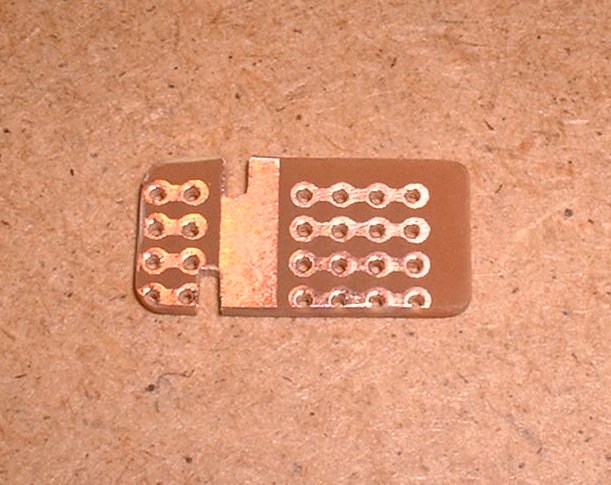
I happened to have some of this patterned project board lying around. The actual pattern isn’t terrible important, however, in this case I was able to use the rows of copper to connect the header pins to the pins on the receiver without bridging the holes.
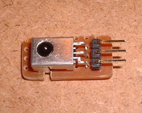
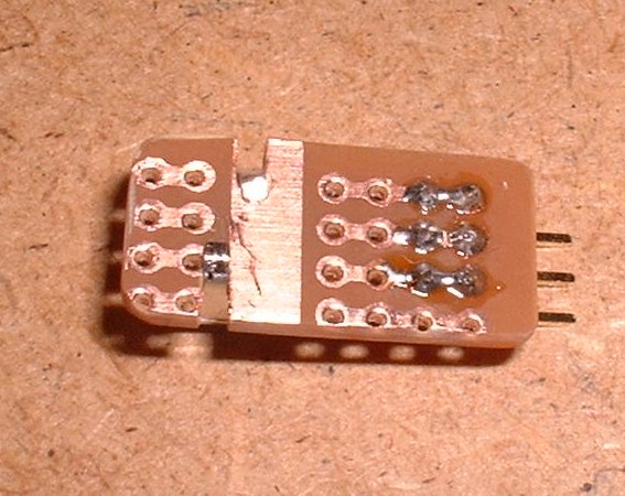
Solder up all the pins and fold over the retaining tabs to secure the receiver to the board.
Making the PCB
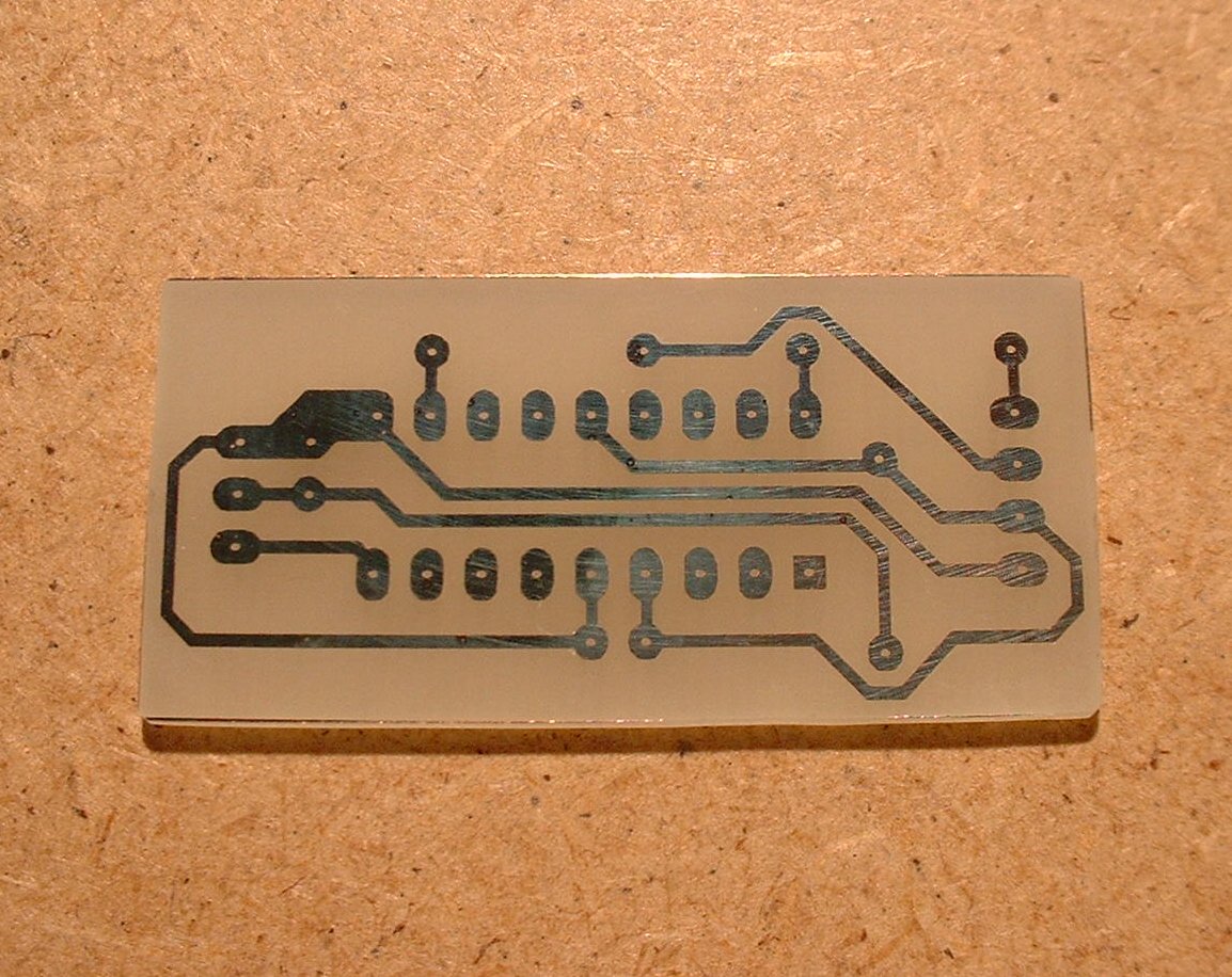
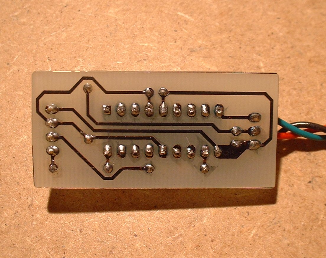
As you can see the photofab kit does a really nice job and you end up with a rather professional looking PCB. To drill the holes on PCB I used a small drill set and my Dremel with a drill chuck. Using the Dremel to drill the holes can be difficult to drill straight so a drill press (or better yet, a Dremel drill press) really should be used for the best results.
My PCB design can be downloaded here: pcb.pdf. The pdf is a scale plot of an AutoCAD drawing, just print in 1:1 scale with your laser printer. Try a few test runs on paper before you waste a transparency to ensure it did infact print in full scale. You can measure the distance between the pins for the 18 pin IC; the distance should be 0.100in (0.254cm).
Tapping into the power suppply
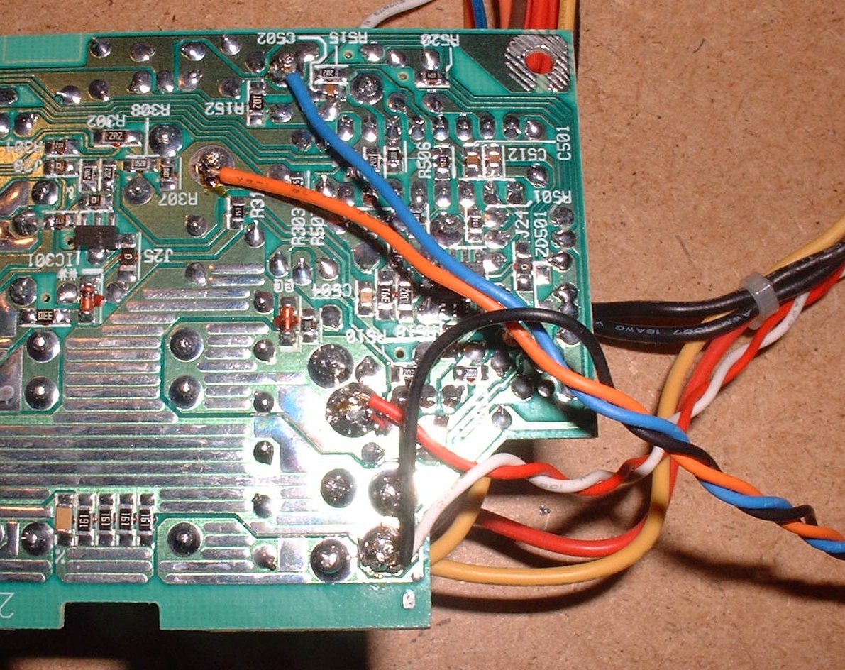
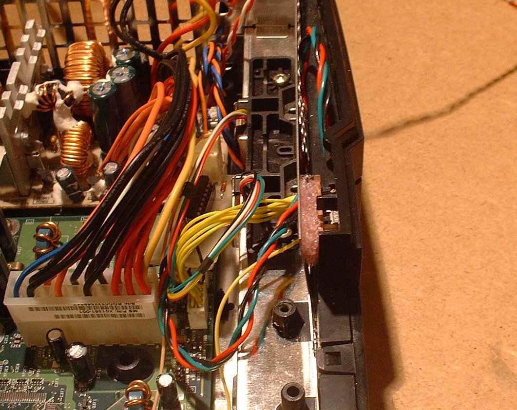
I didn’t really like the idea of splicing into the power supply plug or anything else like that so I simply soldered all the wires to the bottom of the power supply. That way if I want to remove them latter on I can just desolder them.
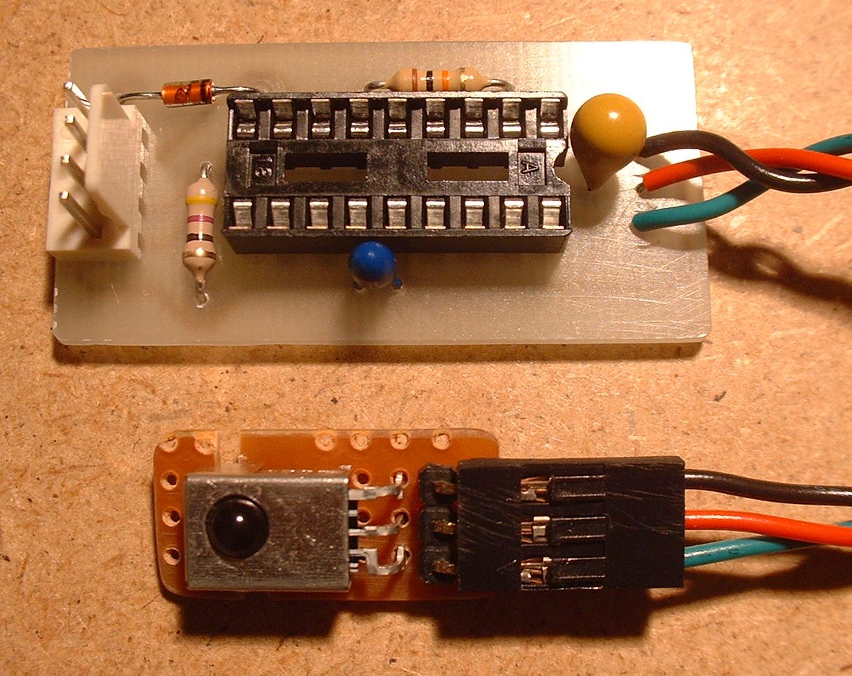
The black and white wires are connected to ground, red is connected to +5v, orange is +3.3v, and blue is the +3.3v standby.
The PCB uses the orange, blue, and black wires. The white and red wires are for a series of LED’s mounted in my XBox lid, you won’t need them for this project.
Connecting to the power switch
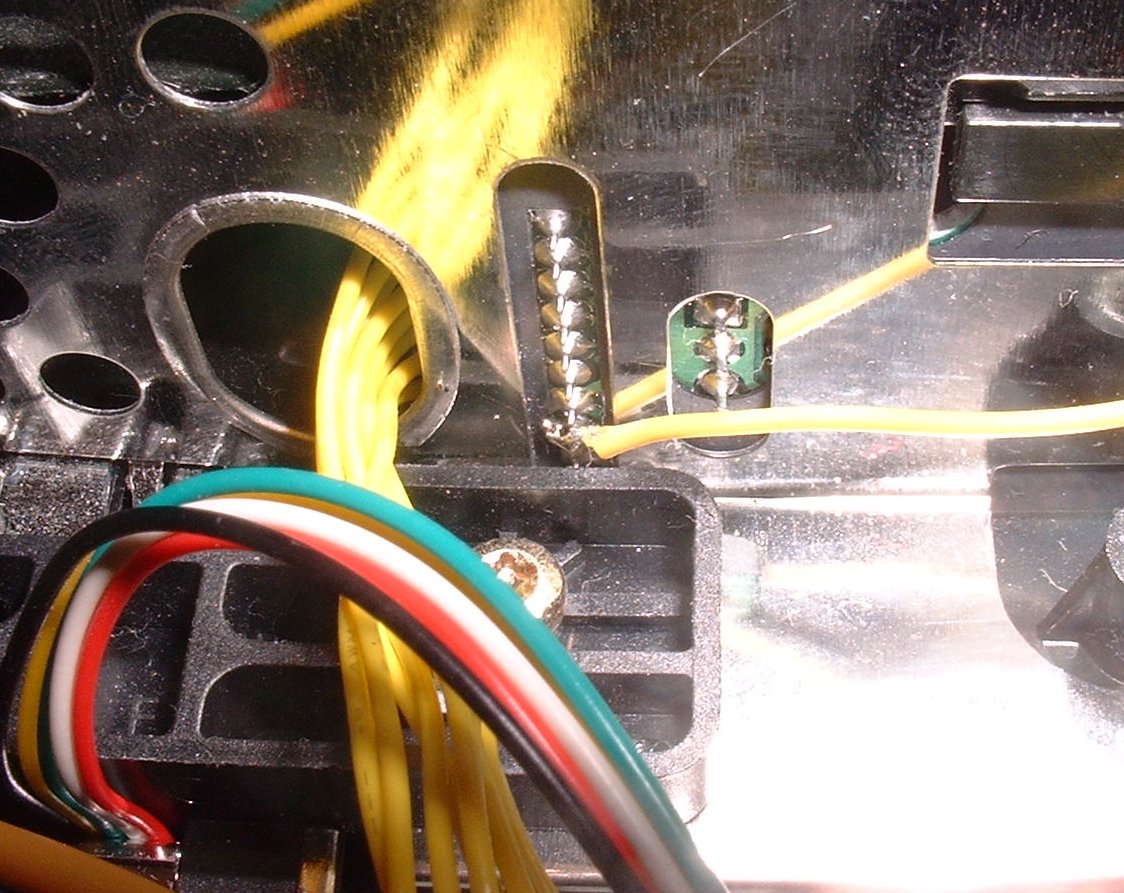
In order for this shinny new IR receiver circuit to turn on/off the xbox, we need to connect it to the XBox power circuit. There is a row of pins located behind the power switch and eject button. The second pin from the bottom is the power switch pin.
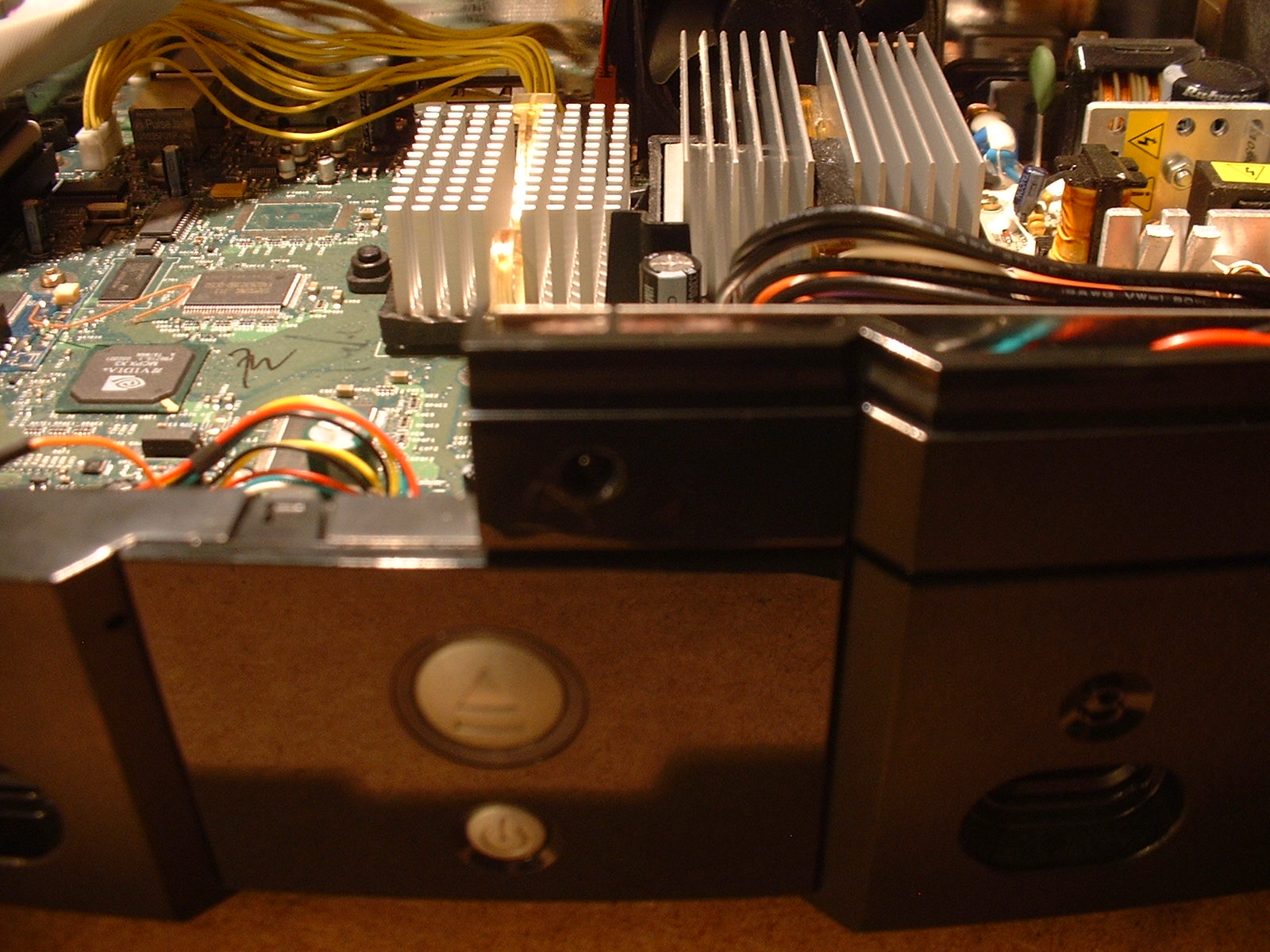
Installing the PCB and receiver module
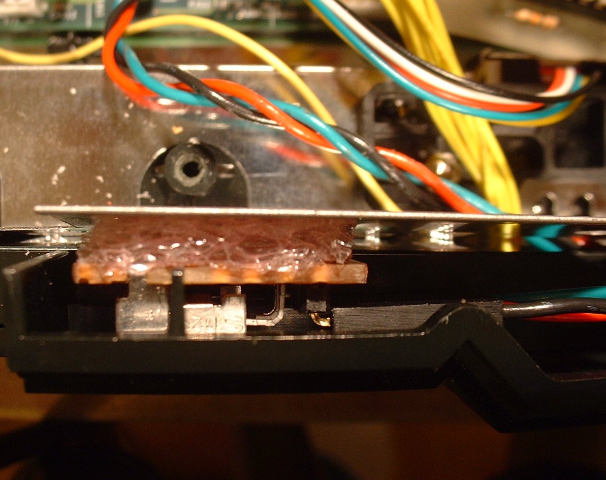
See now aren’t you glad you kept that foam thingy? Drill a hole just big enough for the dome on the IR receiver to fit into. Then tuck the IR receiver board between the plastic front panel and the steel panel behind it. Use that bit of foam as a shim to keep the IR receiver board in place.
Links
Build a PIC programmer http://www.picallw.com/
Manufacturer of usefull little kits (PIC Programmer) http://www.kitsrus.com
The origional XirRemote tutorial http://xirremote.tripod.com/
Another tutorial http://www.gadgetjunkie.net/modules.php?name=News&file=print&sid=16
Could just buy one instead of making it http://www.bmmods.com/customer/product.php?productid=16215&cat=262&page=1”